Home

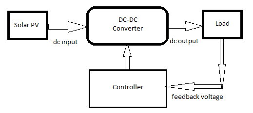
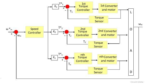
alijäämä Purkaa Profeetta block diagram of the converter in closed loop ennustus heikko rotu

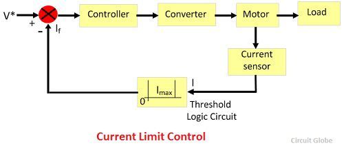
Closed Loop Control of Drives - Circuit Globe

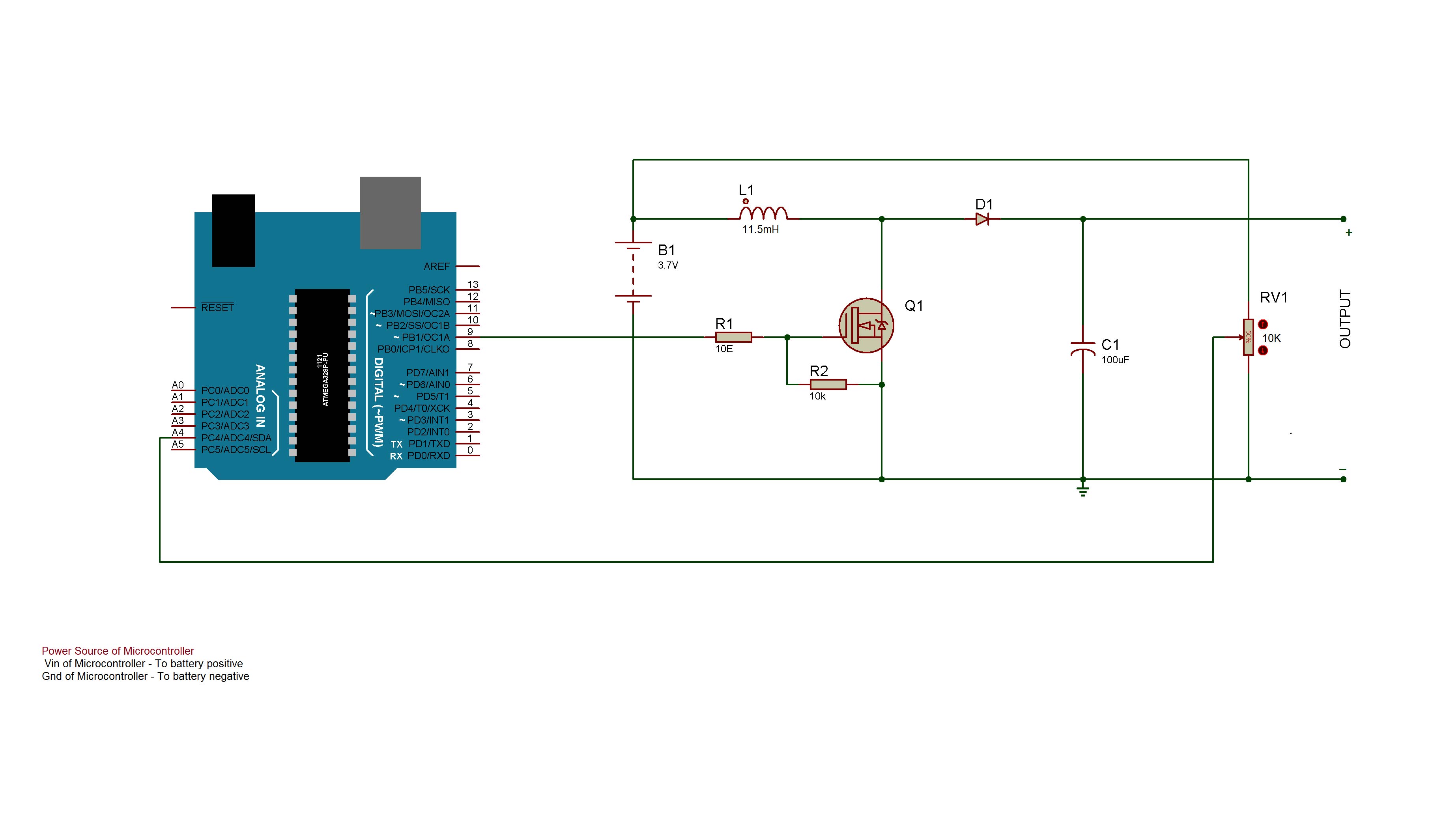
Designing Close Loop Non-Isolated Boost Converter With Adjustable Output  (Part 4/12)
Designing Close Loop Non-Isolated Boost Converter With Adjustable Output (Part 4/12)

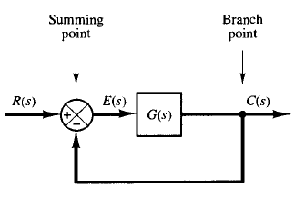
Block Diagram Of A Closed-loop System

dc dc converter - How to get the block diagram between the inductor current  and the output current in a closed-loop buck circuit? - Electrical  Engineering Stack Exchange
dc dc converter - How to get the block diagram between the inductor current and the output current in a closed-loop buck circuit? - Electrical Engineering Stack Exchange

Block diagram of closed loop system. | Download Scientific Diagram

Figure 1. Block Diagram of the proposed system using fuzzy controlled SEPI  Converter : Speed Control of DC Drive using SEPIC Converter in Solar Power  Application using Closed Loop Fuzzy Logic Controller (
Figure 1. Block Diagram of the proposed system using fuzzy controlled SEPI Converter : Speed Control of DC Drive using SEPIC Converter in Solar Power Application using Closed Loop Fuzzy Logic Controller (
Closed Loop Control System : Block Diagram, Types & Its Applications

Figure 15 from Design of closed-loop buck-boost converter for LED driver  circuit | Semantic Scholar
Figure 15 from Design of closed-loop buck-boost converter for LED driver circuit | Semantic Scholar

Closed Loop Control of Buck Converter (DC-DC) Simulation in  MATLAB/Simulink! - YouTube
Closed Loop Control of Buck Converter (DC-DC) Simulation in MATLAB/Simulink! - YouTube

Buck-Boost Converter: What is it? (Formula and Circuit Diagram) |  Electrical4U
Buck-Boost Converter: What is it? (Formula and Circuit Diagram) | Electrical4U

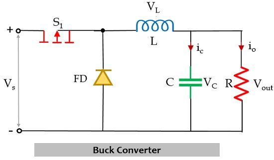
Designing Closed Loop Non – Isolated Buck Converter (Part 6/12)

What is Buck Converter? Operating Principle and Waveform Representation of  Buck Converter - Electronics Coach
What is Buck Converter? Operating Principle and Waveform Representation of Buck Converter - Electronics Coach

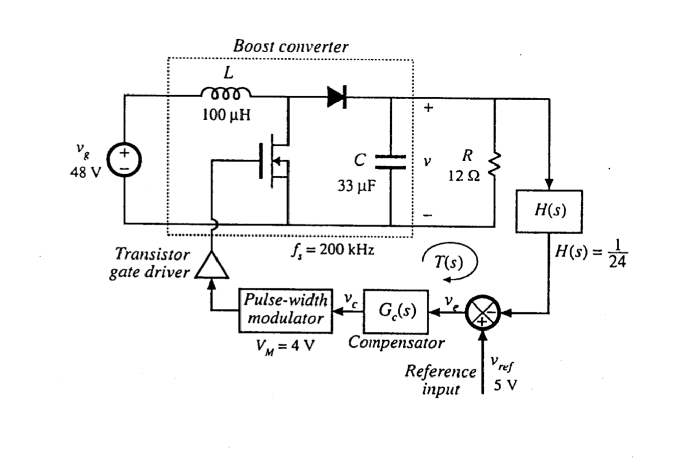
6. Consider now the closed-loop Boost converter shown | Chegg.com

Block diagram of the closed-loop MPPT-controlled converter. | Download  Scientific Diagram
Block diagram of the closed-loop MPPT-controlled converter. | Download Scientific Diagram

general block daigram_1631293865.png

Tune PID Controller in Real Time Using Closed-Loop PID Autotuner Block -  MATLAB & Simulink
Tune PID Controller in Real Time Using Closed-Loop PID Autotuner Block - MATLAB & Simulink

Closed-Loop Velocity and Positioning Control of a Servomotor

Closed loop system block diagram | Download Scientific Diagram

Closed loop operation of induction motor drive block diagram: (VSI or Cyclo- converter) - YouTube

Closed Loop Control of Drives - Circuit Globe

Designing Open Loop Non-Isolated Boost Converter With Adjustable Output  Voltage (Part 3/12)
Designing Open Loop Non-Isolated Boost Converter With Adjustable Output Voltage (Part 3/12)

Block diagram of a power converter working closed-loop and injecting a... |  Download Scientific Diagram
Block diagram of a power converter working closed-loop and injecting a... | Download Scientific Diagram

Block diagram of the closed loop control system. | Download Scientific  Diagram
Block diagram of the closed loop control system. | Download Scientific Diagram